


Kirchhoff’s circuit laws help with the laws and the equation for individual components like capacitor, resistor and inductor. This gives us the basic tool to start analyzing circuits.
A German physicist in 1824 , Gustav Kirchhoff, developed laws that deal with the conservation of energy and current within electrical circuits. These two laws are-
- Kirchhoff’s Voltage Law or Second Law
According to Kirchhoff’s voltage law the sum of the voltages across the closed loop is null.
- Kirchoff’s Current Law or First Law
According to the Kirchoff’s first law the total of the current in a junction is equal to sum of currents outside in a circuit.
These laws help to calculate impedance in the case of AC and the current flow in different network streams or the electrical resistance of a complex network.
Kirchhoff’s Laws
Kirchhoff’s Current Law or First Law
Kirchoffs current law states that the total current flowing a junction or a node is equal to charge of the node as there is no charge lost.
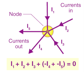
Kirchhoff’s First Law
- According to the above diagram the currents the currents entering the node is equal to the current leaving the node
- The current enter the node as positive and exit as negative. The equation is I1 + I2 + I3 (- I4 – I5) = 0.
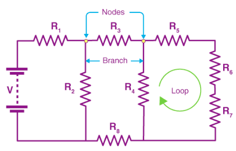
- A node is a junction connecting two or more routes like cables and other components.
- Kirchhoff’s First law can be applied to analyze the parallel circuits.
Kirchhoff’s Voltage Law or Second Law
According to Kirchhoff’s second law the voltage around the loop is equal to the sum of every voltage drop in the same loop of closed network and is equal to zero.
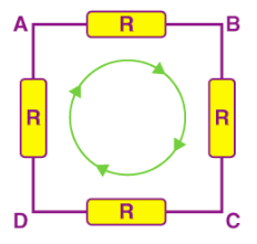
Kirchhoff’s Second Law
- The sum of all voltage drops around the loop is equal to zero.
- Beginning at any point of the loop it continues in the same direction throughout, the voltage drops in negative or positive directions and returns to the same point in the end.
- The direction is either clockwise or counterclockwise for the value to be zero.
- In the diagram, either AC circuit or DC circuit is analyzed based on Kirchhoff’s circuit laws.
Applications of Kirchhoff’s Law
These rules are only useful for characterizing those circuits that cannot be simplified by combining elements in parallel and in series.
- Kirchhoff’s rules are applicable widely and used to solve complex AC circuits problems.
- The both laws of Kirchhoff’s are used in analog electronics for solving complex electrical circuits.
- The laws are used to analyze any AC electrical circuit for those circuits which have electromotive forces, resistors, capacitors, and more.
Solved Example of Kirchhoff’s Law
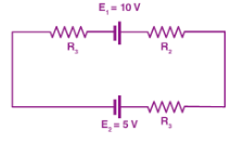
Ques. If R1 = 2Ω, R2 = 4Ω, R3 = 6Ω, determine the electric current that flows in the circuit below.
Ans. According to the law the direction of current is always from positive terminal to negative terminal and the thing we have to keep in mind are:
- One direction needs to be chosen, here we’ll choose a clockwise direction.
- Current will flow across the resistor. Hence, V = IR is negative.
- When the current moves from low to high, then the electromotive source is signed positive because of the energy charging at the source.
- When the current moves from high to low voltage (+ to -), then the source is negative because of the emptying of energy at the emf source.
- The Direction of the current is the same as the direction of clockwise rotation.After Substituting the values in the equation,
–2I + 10 – 4I – 6I – 5 = 0
-12I + 5 = 0
I = -5/-12
I = 0.416 A
- The electric current that flows in the circuit is 0.416 A.
- The electric current is positive which shows that the direction of the electric current is the same as the direction of clockwise rotation.


 : Pics , Bio, Family Life.")


